
Flanged cast bronze bushings – metric sizes and to drawing
A sleeve bushing with a flange at one end: the flange locates the bush against the housing face, stops it walking under oscillation and takes axial thrust that would otherwise need a separate washer. Machined from cast bronze tube in ISO 4379 Series 1 (thin flange) and Series 2 (heavy flange), Ø6 – 200 mm, C93200 / SAE 660 standard, other alloys and any flange to drawing. Solid greased bronze – not a steel-backed or plastic flanged bushing.
- Ø6 – 200mm bore, ISO 4379 Type F
- 2flange series per bore
- d11flange Ø tolerance
- 45 N/mm²static face load, greased
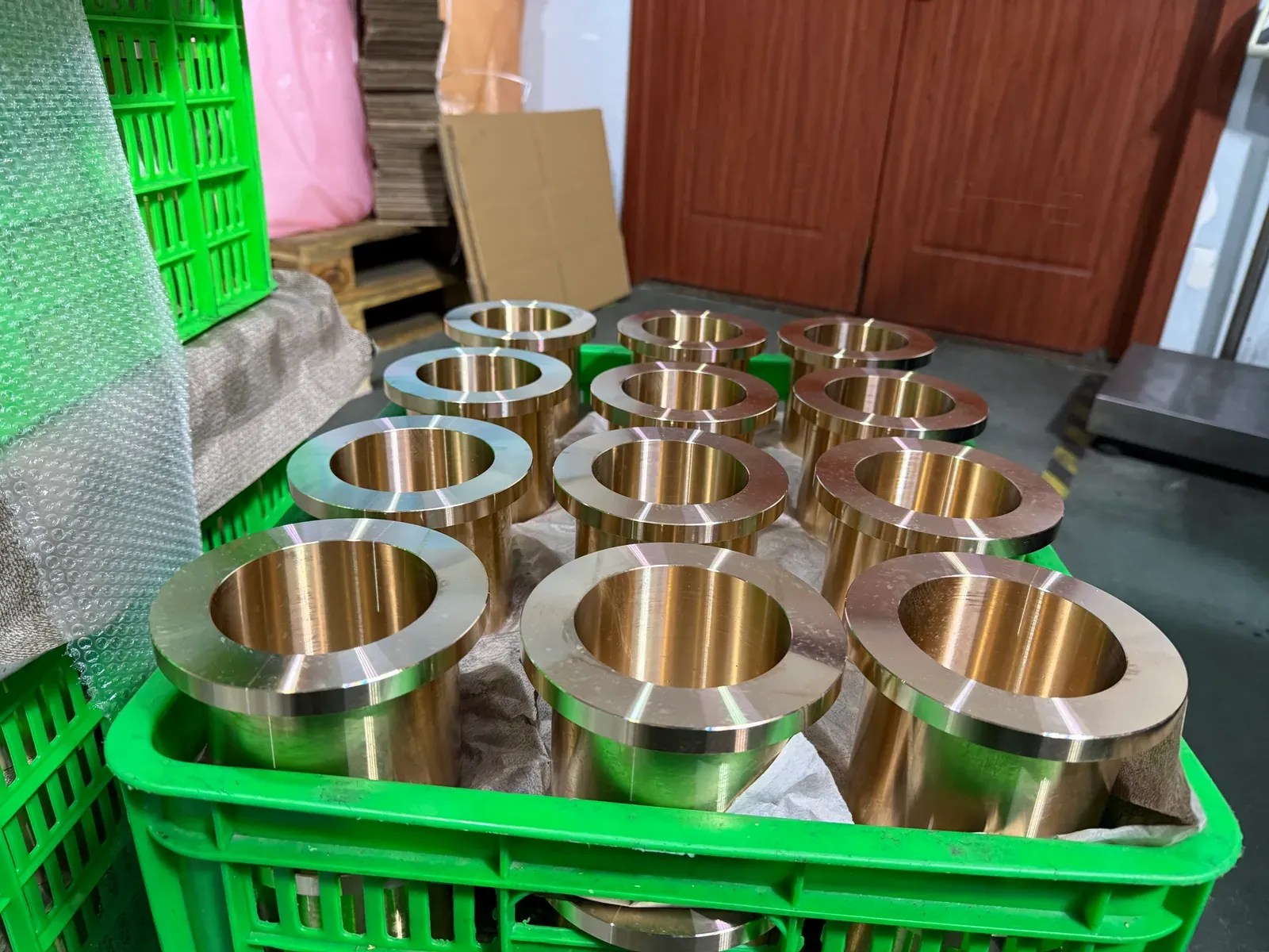
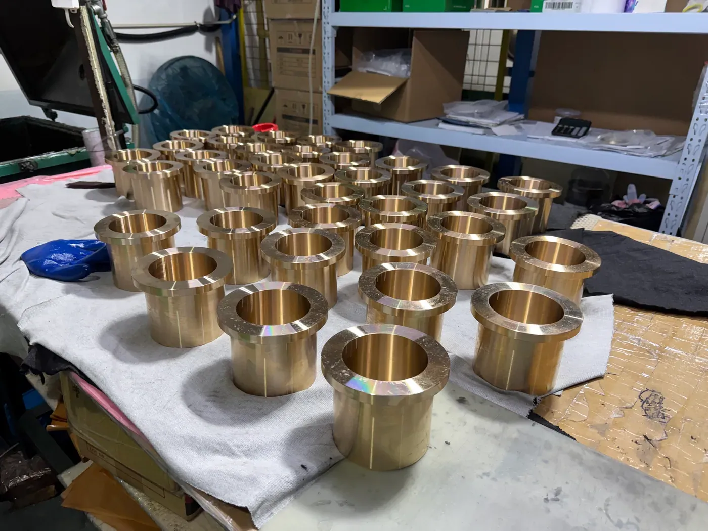
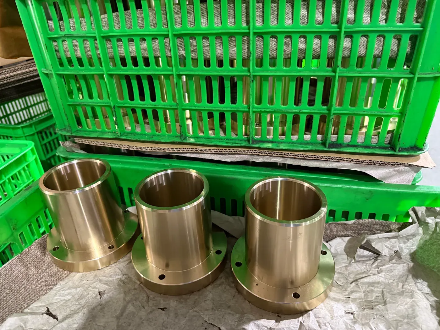
A flanged cast bronze bushing carries radial load on its bore and axial load on the flange face. Five dimensions define it: bore d, outside diameter D, length L including the flange, flange diameter F and flange thickness t. The bush is pressed in from the flange side until the flange sits on the housing face.
- Series 1: thin flange (t = 1 – 5 mm) for location only; Series 2: heavy flange (t = 3 – 15 mm) for axial thrust
- Same bores, walls and tolerances as the sleeve series: bore E6, outside s6 / r6, flange Ø d11, length h13
- Flange face plain, or with radial grease grooves (G7) when it carries load
- Undercut u at the flange root per ISO 4379 – the housing edge needs a matching chamfer or the flange will not seat
- Above Ø120 mm a sleeve plus a separate thrust washer is usually cheaper – the flange wastes bar; see the comparison below
Flanged bronze bushing size chart (mm)
ISO 4379 Table 2, Type F. For every bore the standard gives a Series 1 (thin flange) and a Series 2 (heavy flange) with their own outside diameter, flange diameter and flange thickness. The code carries bore, outside Ø and length; F and t follow from the series: 660F-253230 is Ø25 × Ø32 × 30 with the Series 2 flange Ø38 × 4, 660F-252830 the same bore with the Series 1 flange Ø31 × 1.5.
All dimensions in mm
Type a bore to show only that row; click a length to ask for a quote on that order code.
| Bore d | Series 1 / Series 2 | Outside Ø D | Flange Ø F | Flange t | Lengths L | Weight (kg) | u |
|---|---|---|---|---|---|---|---|
| 6 | Series 1 (thin flange) | 8 | 10 | 1 | 610 | 0.001 – 0.002 | 1 |
| Series 2 (heavy flange) | 12 | 14 | 3 | 610 | 0.006 – 0.009 | ||
| 8 | Series 1 (thin flange) | 10 | 12 | 1 | 610 | 0.002 – 0.003 | 1 |
| Series 2 (heavy flange) | 14 | 18 | 3 | 610 | 0.008 – 0.012 | ||
| 10 | Series 1 (thin flange) | 12 | 14 | 1 | 610 | 0.002 – 0.003 | 1 |
| Series 2 (heavy flange) | 16 | 20 | 3 | 610 | 0.010 – 0.014 | ||
| 12 | Series 1 (thin flange) | 14 | 16 | 1 | 101520 | 0.004 – 0.008 | 1 |
| Series 2 (heavy flange) | 18 | 22 | 3 | 101520 | 0.016 – 0.029 | ||
| 14 | Series 1 (thin flange) | 16 | 18 | 1 | 101520 | 0.005 – 0.009 | 1 |
| Series 2 (heavy flange) | 20 | 25 | 3 | 101520 | 0.019 – 0.033 | ||
| 15 | Series 1 (thin flange) | 17 | 19 | 1 | 101520 | 0.005 – 0.009 | 1 |
| Series 2 (heavy flange) | 21 | 27 | 3 | 101520 | 0.021 – 0.036 | ||
| 16 | Series 1 (thin flange) | 18 | 20 | 1 | 121520 | 0.006 – 0.010 | 1.5 |
| Series 2 (heavy flange) | 22 | 28 | 3 | 121520 | 0.026 – 0.038 | ||
| 18 | Series 1 (thin flange) | 20 | 22 | 1 | 122030 | 0.007 – 0.017 | 1.5 |
| Series 2 (heavy flange) | 24 | 30 | 3 | 122030 | 0.028 – 0.060 | ||
| 20 | Series 1 (thin flange) | 23 | 26 | 1.5 | 152030 | 0.015 – 0.029 | 1.5 |
| Series 2 (heavy flange) | 26 | 32 | 3 | 152030 | 0.036 – 0.065 | ||
| 22 | Series 1 (thin flange) | 25 | 28 | 1.5 | 152030 | 0.017 – 0.031 | 1.5 |
| Series 2 (heavy flange) | 28 | 34 | 3 | 152030 | 0.039 – 0.071 | ||
| (24) | Series 1 (thin flange) | 27 | 30 | 1.5 | 152030 | 0.018 – 0.034 | 1.5 |
| Series 2 (heavy flange) | 30 | 36 | 3 | 152030 | 0.042 – 0.077 | ||
| 25 | Series 1 (thin flange) | 28 | 31 | 1.5 | 203040 | 0.024 – 0.046 | 1.5 |
| Series 2 (heavy flange) | 32 | 38 | 4 | 203040 | 0.068 – 0.12 | ||
| (27) | Series 1 (thin flange) | 30 | 33 | 1.5 | 203040 | 0.026 – 0.050 | 1.5 |
| Series 2 (heavy flange) | 34 | 40 | 4 | 203040 | 0.072 – 0.13 | ||
| 28 | Series 1 (thin flange) | 32 | 36 | 2 | 203040 | 0.037 – 0.071 | 1.5 |
| Series 2 (heavy flange) | 36 | 42 | 4 | 203040 | 0.085 – 0.16 | ||
| 30 | Series 1 (thin flange) | 34 | 38 | 2 | 203040 | 0.040 – 0.076 | 2 |
| Series 2 (heavy flange) | 38 | 44 | 4 | 203040 | 0.090 – 0.17 | ||
| 32 | Series 1 (thin flange) | 36 | 40 | 2 | 203040 | 0.042 – 0.081 | 2 |
| Series 2 (heavy flange) | 40 | 46 | 4 | 203040 | 0.095 – 0.18 | ||
| (33) | Series 1 (thin flange) | 37 | 41 | 2 | 203040 | 0.044 – 0.083 | 2 |
| Series 2 (heavy flange) | 42 | 48 | 5 | 203040 | 0.11 – 0.21 | ||
| 35 | Series 1 (thin flange) | 39 | 43 | 2 | 304050 | 0.067 – 0.11 | 2 |
| Series 2 (heavy flange) | 45 | 50 | 5 | 304050 | 0.18 – 0.30 | ||
| (36) | Series 1 (thin flange) | 40 | 44 | 2 | 304050 | 0.069 – 0.11 | 2 |
| Series 2 (heavy flange) | 46 | 52 | 5 | 304050 | 0.19 – 0.31 | ||
| 38 | Series 1 (thin flange) | 42 | 46 | 2 | 304050 | 0.072 – 0.12 | 2 |
| Series 2 (heavy flange) | 48 | 54 | 5 | 304050 | 0.20 – 0.32 | ||
| 40 | Series 1 (thin flange) | 44 | 48 | 2 | 304060 | 0.076 – 0.15 | 2 |
| Series 2 (heavy flange) | 50 | 58 | 5 | 304060 | 0.22 – 0.41 | ||
| 42 | Series 1 (thin flange) | 46 | 50 | 2 | 304060 | 0.079 – 0.15 | 2 |
| Series 2 (heavy flange) | 52 | 60 | 5 | 304060 | 0.23 – 0.43 | ||
| 45 | Series 1 (thin flange) | 50 | 55 | 2.5 | 304060 | 0.11 – 0.21 | 2 |
| Series 2 (heavy flange) | 55 | 63 | 5 | 304060 | 0.24 – 0.45 | ||
| 48 | Series 1 (thin flange) | 53 | 58 | 2.5 | 405060 | 0.15 – 0.22 | 2 |
| Series 2 (heavy flange) | 58 | 66 | 5 | 405060 | 0.33 – 0.48 | ||
| 50 | Series 1 (thin flange) | 55 | 60 | 2.5 | 405060 | 0.16 – 0.23 | 2 |
| Series 2 (heavy flange) | 60 | 68 | 5 | 405060 | 0.34 – 0.50 | ||
| 55 | Series 1 (thin flange) | 60 | 65 | 2.5 | 405070 | 0.17 – 0.29 | 2 |
| Series 2 (heavy flange) | 65 | 73 | 5 | 405070 | 0.38 – 0.63 | ||
| 60 | Series 1 (thin flange) | 65 | 70 | 2.5 | 406080 | 0.19 – 0.36 | 2 |
| Series 2 (heavy flange) | 75 | 83 | 7.5 | 406080 | 0.63 – 1.2 | ||
| 65 | Series 1 (thin flange) | 70 | 75 | 2.5 | 506080 | 0.25 – 0.39 | 2 |
| Series 2 (heavy flange) | 80 | 88 | 7.5 | 506080 | 0.83 – 1.3 | ||
| 70 | Series 1 (thin flange) | 75 | 80 | 2.5 | 507090 | 0.27 – 0.47 | 2 |
| Series 2 (heavy flange) | 85 | 95 | 7.5 | 507090 | 0.91 – 1.6 | ||
| 75 | Series 1 (thin flange) | 80 | 85 | 2.5 | 507090 | 0.29 – 0.50 | 3 |
| Series 2 (heavy flange) | 90 | 100 | 7.5 | 507090 | 0.97 – 1.7 | ||
| 80 | Series 1 (thin flange) | 85 | 90 | 2.5 | 6080100 | 0.36 – 0.59 | 3 |
| Series 2 (heavy flange) | 95 | 105 | 7.5 | 6080100 | 1.2 – 1.9 | ||
| 85 | Series 1 (thin flange) | 90 | 95 | 2.5 | 6080100 | 0.38 – 0.63 | 3 |
| Series 2 (heavy flange) | 100 | 110 | 7.5 | 6080100 | 1.3 – 2.1 | ||
| 90 | Series 1 (thin flange) | 100 | 110 | 5 | 6080120 | 0.87 – 1.7 | 3 |
| Series 2 (heavy flange) | 110 | 120 | 10 | 6080120 | 1.8 – 3.5 | ||
| 95 | Series 1 (thin flange) | 105 | 115 | 5 | 60100120 | 0.92 – 1.8 | 3 |
| Series 2 (heavy flange) | 115 | 125 | 10 | 60100120 | 1.9 – 3.7 | ||
| 100 | Series 1 (thin flange) | 110 | 120 | 5 | 80100120 | 1.3 – 1.8 | 3 |
| Series 2 (heavy flange) | 120 | 130 | 10 | 80100120 | 2.6 – 3.9 | ||
| 105 | Series 1 (thin flange) | 115 | 125 | 5 | 80100120 | 1.3 – 1.9 | 3 |
| Series 2 (heavy flange) | 125 | 135 | 10 | 80100120 | 2.8 – 4.1 | ||
| 110 | Series 1 (thin flange) | 120 | 130 | 5 | 80100120 | 1.4 – 2.0 | 3 |
| Series 2 (heavy flange) | 130 | 140 | 10 | 80100120 | 2.9 – 4.2 | ||
| 120 | Series 1 (thin flange) | 130 | 140 | 5 | 100120150 | 1.8 – 2.7 | 3 |
| Series 2 (heavy flange) | 140 | 150 | 10 | 100120150 | 3.9 – 5.7 | ||
| 130 | Series 1 (thin flange) | 140 | 150 | 5 | 100120150 | 2.0 – 2.9 | 4 |
| Series 2 (heavy flange) | 150 | 160 | 10 | 100120150 | 4.1 – 6.1 | ||
| 140 | Series 1 (thin flange) | 150 | 160 | 5 | 100150180 | 2.1 – 3.8 | 4 |
| Series 2 (heavy flange) | 160 | 170 | 10 | 100150180 | 4.4 – 7.8 | ||
| 150 | Series 1 (thin flange) | 160 | 170 | 5 | 120150180 | 2.7 – 4.0 | 4 |
| Series 2 (heavy flange) | 170 | 180 | 10 | 120150180 | 5.6 – 8.3 | ||
| 160 | Series 1 (thin flange) | 170 | 180 | 5 | 120150180 | 2.9 – 4.3 | 4 |
| Series 2 (heavy flange) | 185 | 200 | 12.5 | 120150180 | 7.8 – 11.4 | ||
| 170 | Series 1 (thin flange) | 180 | 190 | 5 | 120180200 | 3.1 – 5.0 | 4 |
| Series 2 (heavy flange) | 195 | 210 | 12.5 | 120180200 | 8.2 – 13.3 | ||
| 180 | Series 1 (thin flange) | 190 | 200 | 5 | 150180250 | 4.0 – 6.6 | 4 |
| Series 2 (heavy flange) | 210 | 220 | 15 | 150180250 | 12.8 – 21.0 | ||
| 190 | Series 1 (thin flange) | 200 | 210 | 5 | 150180250 | 4.2 – 7.0 | 4 |
| Series 2 (heavy flange) | 220 | 230 | 15 | 150180250 | 13.4 – 22.0 | ||
| 200 | Series 1 (thin flange) | 210 | 220 | 5 | 180200250 | 5.3 – 7.3 | 4 |
| Series 2 (heavy flange) | 230 | 240 | 15 | 180200250 | 16.8 – 23.1 |
No ISO 4379 size with this bore – send us the dimensions, we machine it to drawing.
Bore in parentheses in ISO 4379: for special applications only.
Weight per piece in kg, plain part in C93200 (8.93 g/cm³); aluminium bronze is about 16 % lighter, SAE 67 about 4 % heavier.
Inch sizes, other flange diameters, flanges with bolt holes or grease grooves and bores above Ø200 mm are machined to drawing.
Operating limits (greased)
The bore is designed like a sleeve bushing. For the flange, divide the axial force by the flange ring area π/4 × (F² − D²) and compare with the same specific-load limits; the face speed is taken at the mean flange diameter.
| Parameter | Typical | Unit |
|---|---|---|
| Specific load p, moving | 25 | N/mm² |
| Specific load p, stationary | 45 | N/mm² |
| Sliding speed v | 0.5 | m/s |
| Coefficient of friction | 0.08 – 0.15 | µ |
| Working temperature | −40 … +250 | °C |
| Housing | H7 | ISO 286 |
| Shaft | e7–e8 | ISO 286 |
| Condition | grease or oil, boundary lubrication, steel shaft | |
The limits below are the general values for greased cast bronze; whether the flange face can carry the full moving load depends on grease reaching it – give the face radial grooves (G7) above about 5 N/mm².
How much axial load the flange takes
Axial capacity is a matter of face area and lubrication. Example: a Series 2 flange for a Ø50 bore has D = 60, F = 68 – a ring area of π/4 × (68² − 60²) = 804 mm². At the 25 N/mm² moving limit that is 20 kN; at 45 N/mm² stationary, 36 kN. Series 1 at the same bore (D = 55, F = 60) has 452 mm², so about half.
The face runs against the shaft collar or a hardened washer, not against the housing – the housing side is static. Grease reaches the face only if it is grooved or the collar is: on a rotating shaft with more than light thrust we cut two to four radial grooves (G7) and a chamfer at the bore edge; on an oscillating pin the grease from the bore usually suffices.
The flange also takes the axial component of misaligned pins and keeps the bush from walking out of a blind housing. Thickness t is set by ISO 4379; for shock loads specify Series 2 or a thicker flange to drawing – a thin flange in soft C93200 will flow under repeated impact.
For your enquiry:Send the axial force and whether the shaft rotates or oscillates – we size the flange and grooves.
Flanged bushing or sleeve plus thrust washer?
Both carry radial and axial load. The choice is about assembly, wear and bar cost:
| Criterion | Flanged bushing | Sleeve + thrust washer |
|---|---|---|
| Parts and assembly | one part, self-locating, pressed from the flange side | two parts; washer needs a pin, tab or counterbore against rotation |
| Replacement after face wear | whole bush comes out | washer alone is changed; bush stays |
| Thrust in both directions | one direction only (second washer needed) | a washer each side |
| Bar cost above Ø120 mm | flange dictates a much larger bar – expensive | sleeve from tube, washer from plate or ring – cheaper |
| Face grooves | G7 on the flange face, on request | standard on grooved washers |
| Typical use | pins, small gearboxes, agricultural pivots, Ø6 – 120 | large slow shafts, mills, cranes, everything above Ø120 |
Installation tips
Press from the flange side with a mandrel that bears on the flange face, never on the bronze bore edge; the flange must sit flat on a housing face that is square to the bore (0.05 mm / 100 mm is a practical limit) or it will crack or carry on one side. The housing edge needs a chamfer or counterbore that clears the undercut u at the flange root – a sharp housing edge stops the flange 1 – 2 mm short.
Housing H7 and shaft e7 / e8 as for sleeve bushings; the bore closes to about H8 after pressing. When the flange takes thrust, harden the collar or add a hardened steel washer (min. 300 HB) between collar and bronze; grease reaches the face through G7 grooves.
Alloys for flanged bushings
C93200 / SAE 660 is the default and right for most pins and pivots. Move to C86300 or aluminium bronze when the flange takes shock thrust (crusher and press linkages), to aluminium bronze in seawater and above 150 °C, to LG2 / C83600 in pump and valve positions with water and light load, and to a tin bronze when the drawing is lead-free. The alloy overview has the properties table.
How to order a flanged bushing
Pick the size and series in the table, or send the five dimensions d × D × L and F × t. For thrust duty add the axial force.
Example
660F-253230C93200 flanged bushing Ø25 bore × Ø32 outside × 30 long including the Series 2 flange Ø38 × 4 mm.
- Order code, or d × D × L plus F × t (mm or inch)
- Alloy – C93200 unless stated
- Axial load and shaft movement (rotating / oscillating) if the flange carries thrust
- Face grooves G7 yes / no; oil hole position
- Quantity now and per year, delivery country
Where flanged bushings are used
Wherever a pin or shaft has to be located axially without a separate washer:
- Agricultural machineryThree-point linkage, header and baler pivots, steering pins on tractors and trailers
- Construction and mining machinerySmall excavator and loader pins, cylinder eyes, pedal and lever pivots
- Pumps, valves and hydraulicsValve stem guides, gearbox and pump end bushes with thrust
- Steel mills, sugar mills, heavy industryTable roller and guide bushes up to Ø120; larger positions use sleeve plus washer
Frequently asked questions
What is a flanged bushing used for?
To carry a radial load on the bore and locate the shaft or the bush axially on the flange at the same time. The flange stops the bush walking out under oscillation, takes light to medium axial thrust, and gives a defined stop when pressing the bush in. Typical positions: pins, levers, small gearbox shafts, valve stems.
Should I grease a flanged bronze bushing?
Yes – solid cast bronze is not self-lubricating. Grease the bore through an oil hole and grooves; if the flange face carries thrust give it radial grooves so grease reaches the face. Only oil-impregnated sintered bushings run without external grease, and they carry far less load.
Can the flange have grease grooves?
Yes. Two to four radial grooves (pattern G7), 1 – 3 mm wide depending on size, stopped short of the outer edge, are cut on request. Order them when the face pressure exceeds about 5 N/mm² or the shaft rotates continuously.
Do you make flanged bushings above Ø100 mm?
Yes, ISO 4379 lists them to Ø200 mm and we machine to Ø1000 mm to drawing. Above about Ø120 mm consider a sleeve plus a separate thrust washer: the flange forces a much bigger bar and the washer can be replaced alone.
Do you also make steel-backed or plastic flanged bushings?
Not on this site – this range is solid cast bronze. Wrapped bronze, bimetal, graphite-plugged and metal-polymer flanged bushings are made by our sister ranges; the types page compares the six constructions and links to them.
Not sure which form?
Send the assembly sketch or the old part's dimensions – we suggest flanged bushing or sleeve plus washer, and quote both.